Task 1
Understanding various methods of filtering
INTRODUCTION TO FILTERS
-
Filters are circuits that can isolate certain frequencies in order to reject/ amplify them from a digital audio signal.
-
Applications include:
- Radio Communications: Rejects all the frequencies apart from the desired signal.
- DC power supplies: Used to eliminate noise in high frequency present in AC input.
- Audio electronics: Used to channel different ranges of frequencies to woofers, speakers and tweeters.
- Analog-to-digital conversion: Filters are placed in front of an ADC input to minimize aliasing.
-
Some of the important terms are:
- Response Curves: Response curves are used to describe how a filter behaves. A response curve is simply a graph showing an attenuation ratio (VOUT / VIN) versus frequency . Attenuation is commonly expressed in units of decibels (dB). Frequency can be expressed in two forms: either the angular form ω (units are rad/s) or the more common form of f (units of Hz, i.e.. cycles per second).
- Bandwidth (β or B.W.): The bandwidth is the width of the passband, and the passband is the band of frequencies that do not experience significant attenuation when moving from the input of the filter to the output of the filter.
- Stopband frequency (fs): This is a particular frequency at which the attenuation reaches a specified value.
- For low-pass and high-pass filters, frequencies beyond the stopband frequency are referred to as the stopband.
- For band-pass and notch filters, two stopband frequencies exist. The frequencies between these two stopband frequencies are referred to as the stopband.
TYPES OF FILTERS
-
Low Pass Filters
-
High-pass Filters
-
Bandpass Filters
-
Band-reject Filters/Notch Filters
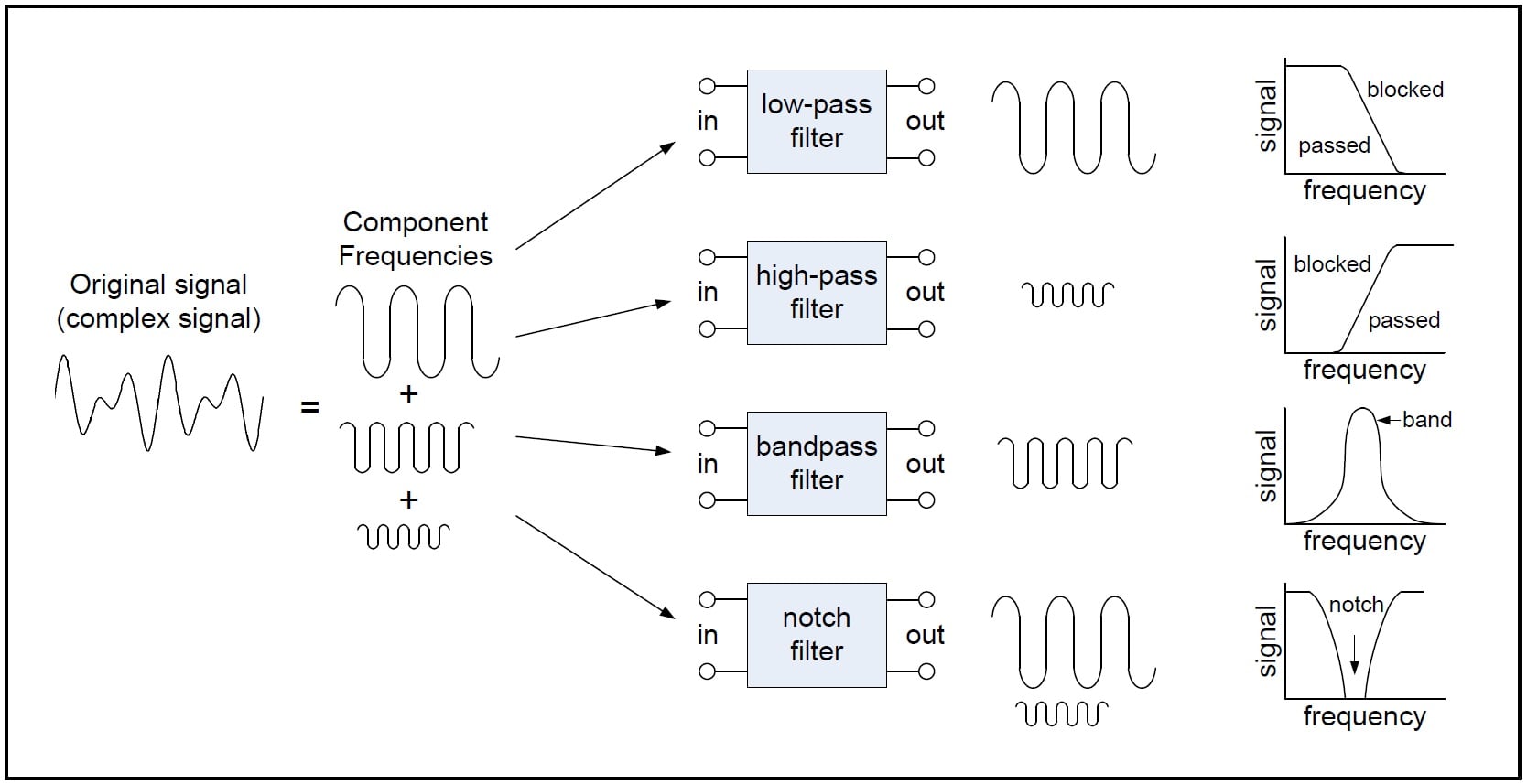
Different types of filters
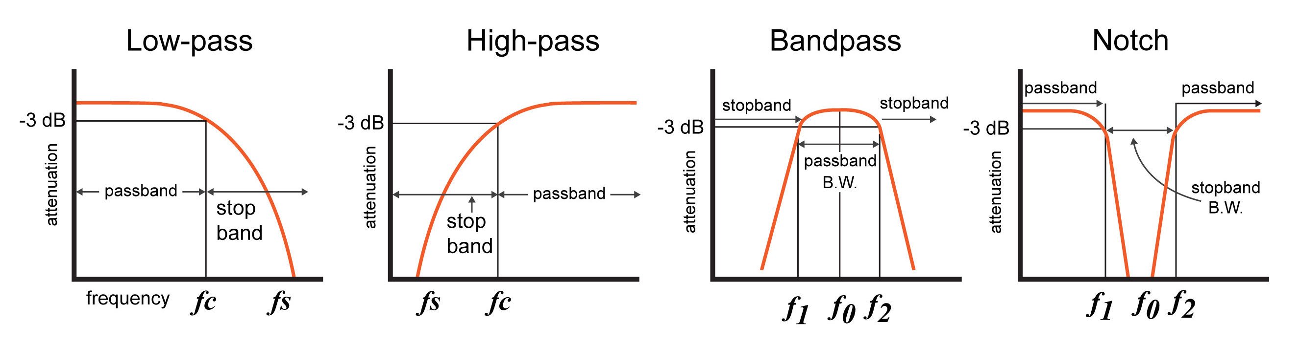
Response curves of the different filters
-
They can also be classified as:
- Finite Impulse Response filters
- Infinite Impulse Response filters
FINITE IMPULSE RESPONSE FILTERS (FIR)
-
Impulse response of finite duration.
-
Provide Linear phase characteristics.
-
Always stable.
-
Can be used for more complex circuits.
INFINITE IMPULSE RESPONSE FILTERS (IIR)
- Impulse response of infinite duration.
- Non linear phase characteristics.
- They are unstable.
- Used for less complexity.
IIR FILTERS
BUTTERWORTH FILTERS
-
Designed to have a frequency response as flat as possible in the passband.
-
The frequency response of the Butterworth filter is maximally flat ( has no ripples) in the passband and rolls off towards zero in the stopband.

CHEBYSHEV FILTERS
- Have a steeper roll off than Butterworth filters.
- Minimise the error between the idealized and the actual filter characteristic over the range of the filter with ripples in passband.
- Because of presence of ripple in the pass band, it is not chosen in applications needing smoother response in passband.

ELLIPTIC FILTERS
- Equalised ripple behaviour in both passband and stop band.
- The amount of ripple in each band is independently adjustable, and no other filter of equal order can have a faster transition in gain between the passband and the stopband, for the given values of ripple.
- As the ripple in the stopband approaches 0, the filter becomes a type I Chebyshev filter.
- As the ripple in the passband approaches 0, the filter becomes a type II Chebyshev filter.
- As both ripple values approach 0, the filter becomes a Butterworth filter.

BESSEL FILTER
-
Analog linear filter with a maximally flat group/phase delay (maximally linear phase response), which preserves the wave shape of filtered signals in the passband.
-
Transition from the pass band to the stop band is much slower than for other filters.
-
But the group delay is practically constant in the passband.
-
Maximizes the flatness of the group delay curve at zero frequency.

A plot of the gain and group delay for a fourth-order low pass Bessel filter.
FIR FILTERS
HAMMING AND HANNING WINDOWS
-
Window function is a mathematical function that is zero-valued outside of some chosen interval, normally symmetric around the middle of the interval, usually near a maximum in the middle, and usually tapering away from the middle.

HANNING WINDOW

HAMMING WINDOW

DIFFERENCE
- Hanning window touches zero at both ends, removing any discontinuity. The Hamming window stops just shy of zero, meaning that the signal will still have a slight discontinuity.

COMPARING IIR FILTERS
-
Here is an image showing the gain of a discrete-time Butterworth filter next to other common filter types. All of these filters are fifth-order.
-
The Butterworth filter rolls off more slowly around the cut-off frequency than the Chebyshev filter or the Elliptic filter, but without ripple.
-
Chebyshev filters are sharper than the Butterworth filter; they are not as sharp as the elliptic one, but they show fewer ripples over the bandwidth.
-
Elliptic filters are sharper than all the others, but they show ripples on the whole bandwidth.

ADVANTAGES OF IIR OVER FIR FILTERS
- IIR filters achieve desired filtering characteristics using lesser memory.
- Has higher computational efficiency and shorter delay.
- Can be used to implement analog filter responses.